Improvement of Carburizing and Quenching Taper Deformation of Driven Gear
With the great development of domestic railways, there are more and more locomotive gear products. In the manufacture of hardened gears, carburizing and quenching is an important method of hardening the tooth surface. From the standpoint of strength, carburizing has the best comprehensive mechanical properties. Therefore, carburizing and quenching is still commonly used as the tooth surface for locomotive gears. Surface hardening method. However, due to the complex hardening process of carburizing and quenching gears, the gears are prone to deformation, which will not only increase the subsequent grinding volume and increase production costs, but also affect the manufacturing accuracy of the gears, reduce the load-bearing capacity, and ultimately affect the service life of the gears. Therefore, in the gear industry, reducing gear carburizing and quenching distortion has always been an important topic for heat treatment workers.
This paper analyzes the problem of large heat treatment deformation of a certain type of locomotive driven gear in the actual production process, proposes improvement measures, and conducts experimental verification.
- Gear related parameters and heat treatment process
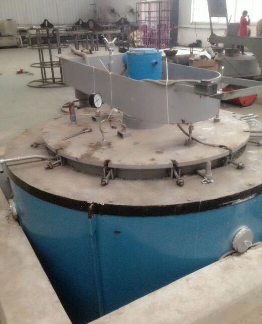
The structure of the driven gear of a certain locomotive is shown in Figure 1. The weight of the gear is 350kg and the material is 18CrNiMo7-6. Carburizing and quenching are carried out using the well-type carburizing furnace production line of Hangzhou Ruiqin Mechanical Equipment Co., Ltd., and the quenching medium is rapid quenching oil.
Heat treatment technical requirements: effective hardened layer depth 1.6~2.2mm, single side grinding amount 0.35~0.45mm when grinding teeth. The metallographic organization meets the requirements of ISO 6336-5 MQ level and above.
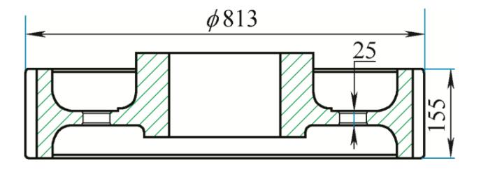
Figure 1. Schematic diagram of gear structure
Gear manufacturing process: tooth blank forging → preliminary heat treatment → semi-finishing turning → hobbing → carburizing and quenching → shot peening → fine turning → gear grinding → magnetic particle inspection.
During trial production, the heat treatment process of the gear: carburized at 920°C, cooled to 860°C and slowly cooled, tempered at a high temperature of 640°C, reheated and quenched, and tempered at low temperature twice. The state of the carburizing and quenching clamps is shown in Figure 2.
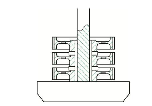
FIG. 2 Schematic diagram of carburizing and hardening clamping
- Heat treatment deformation and analysis
Gear deformation after carburizing and quenching. The gear has undergone a large taper deformation, as shown in Figure 3. After heat treatment, the common normal line differs greatly along the tooth height direction. After the tooth is ground, the effective hardened layer depth of the tooth surface is uneven.
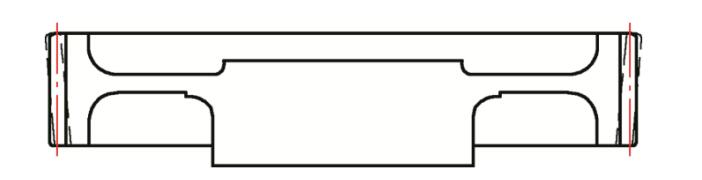
FIG. 3 Gear distortion trend after heat treatment (dotted line)
The taper deformation after carburizing is caused by the creep caused by the gear’s own weight at high temperature for a long time. The so-called creep is the process of increasing the deformation of the material over time under the action of high temperature and constant value of stress. Steel has very low strength at high temperatures. This gear is a thin-web driven gear, and the minimum web thickness is only 25mm. Due to the lack of adequate support at the gear teeth, the strength of the gear web is greatly reduced at high temperatures and cannot withstand the action of gravity. During the long-term carburizing process, the gear creep causes serious taper deformation.
When parts are quenched, the tooth width is unevenly cooled, and the half that is cooled first shrinks. Under the control of the hot side, the cold side is subjected to tensile stress, while the hot side is subjected to compressive stress. The hot edge is compressed due to its better plasticity at high temperatures. After cooling to a certain degree, the hot side begins to cool, and shrinkage also occurs. At this time, the stress state changes, first the cold side is compressive stress, and then the cold side is tensile stress. In the later stage of cooling, due to the lower temperature, no obvious plastic elongation can be produced, and the original compressed amount cannot be offset. No obvious plastic growth and shortening can occur at the first cold edge. Therefore, the final result of the workpiece cooling is the first cold edge. It shrinks and then expands on the cold side.
- Improvement measures
When carburizing, the solution to this problem is to add a wedge-shaped block support at the gear teeth.
During the quenching and clamping, the upward direction of the gear is reversed to the carburizing direction, so that the taper deformation caused by the weight of the part of the carburizing can be reversely corrected during the quenching and heat preservation. After the improvement, the gear clamping diagram is shown in Figure 4 and Figure 5.
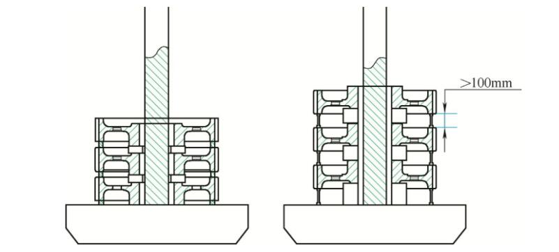
FIG 4. Carburizing and clamping of gear FIG. 5. Hardening and clamping of gear
During quenching and heating, the interval between the two gear teeth is increased from the original 50mm to 100mm to improve the flow of quenching oil during oil quenching, so that the gears are cooled uniformly throughout and the increase in each location tends to be the same.
After improvement, the heat treatment deformation is shown in Table 2. It can be seen from Table 2 that after carburizing, the deformation of the upper and lower taper of the gear does not change much. But after quenching, the average value of the deformation of the upper and lower taper of the gear is reduced by 0.296mm, and the deformation is reduced by 64%.
- Conclusion
(1) When the gear is clamped, use flat wedge-shaped pads to support the teeth, which can ensure the strength of the thin-web integral driven gear rim during the carburizing process and reduce the deformation due to its own weight.
(2) During quenching, the gear clamping and carburizing are reversed, which can effectively improve the taper deformation during carburizing.
(3) During quenching, the upper and lower spacing of the gear should meet the process requirements to ensure uniform cooling of the gear during quenching.
(4) After carburizing and quenching, the deformation should be measured in time, and the heat treatment process and furnace installation method should be adjusted in time according to the measurement results.
Vacuum Drying Process Of Oil – Immersed Transformer 20Cr2Ni4 Steel Gear Carburizing and Quenching Process Study Gear Carburizing Heat Treatment Furnace Structure Composition And introduction
Contact us
Your email address will not be published. Required fields are marked *