Gear Carburizing Heat Treatment Furnace Structure Composition And introduction
1. Device application
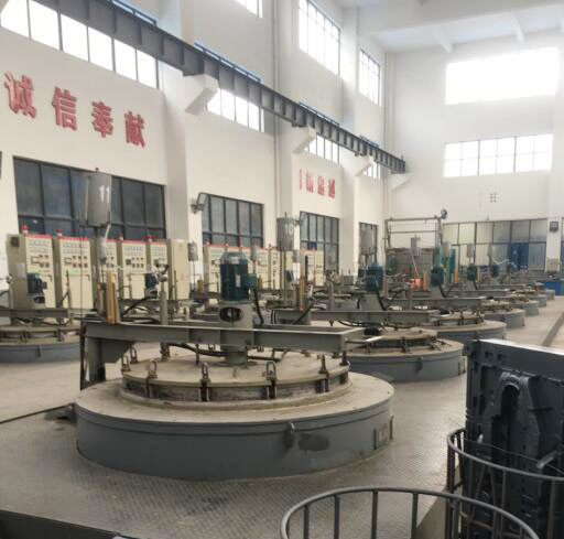
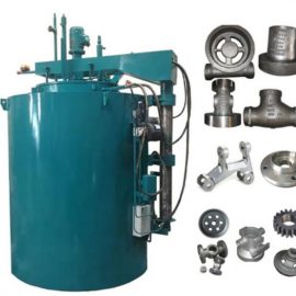
This series of well-type gas carburizing furnaces and carbonitriding furnaces have introduced advanced design concepts from abroad, adhering to the characteristics of high performance and high automation of European industrial furnaces. Steel quenching and tempering and quenching and other heat treatment processes.
2. Equipment composition:
This series of carburizing furnace consists of furnace body (including furnace bottom and heating elements), muffle tank, material storage tray, air guide tube, furnace cover and furnace cover lifting and rotating device, fast cooling air supply and exhaust system, temperature control and electrical It is composed of control system, carbon potential control system and gas supply system, computer and PE expert system.
3. Equipment introduction:
3.1. The furnace shell is welded by section steel and high-quality steel plate. The lining wall is made of ceramic refractory fibers and clay bricks. The bottom of the furnace is made of three kinds of materials: the bottom layer is built with heavy refractory clay bricks and light insulation bricks at intervals, and the upper layer is built with high-strength anti-carburizing refractory bricks.
3.2. The heating device is evenly arranged around the furnace lining wall. The heating device is made of high-temperature electrothermal alloy wire wound into a spiral shape and distributed in the heating area. The installation method ensures heating uniformity, service life and high reliability. Maintenance is very convenient. Each heating zone is equipped with a thermocouple for temperature measurement and over-temperature alarm. At the same time, considering the interchangeability of heating elements, each group of heating elements in each zone has the same parameters and the same structure, so that the performance of the heating elements is consistent and the complexity of spare parts for users is reduced.
3.3 The muffle tank adopts a bottomed muffle structure. The muffle tank is hoisted in the heating furnace. There is a water-cooled ceramic fiber braided rope at the tank mouth to form an effective seal between the furnace cover and the muffle tank to ensure that the heat treatment atmosphere is at Good working condition. There is also a ring of nitrogen at the mouth of the tank to prevent violent noise and protect the sealing ring when the furnace cover is opened.
3.4 The furnace cover is equipped with a guide device for lifting and guiding. The lifting and rotating mechanism is composed of hydraulic pump station, oil cylinder and valve components, limit travel switch and offside travel switch. The furnace cover is a water-cooled sealed flange structure, which is located on the ceramic fiber braided rope of the upper flange of the muffle. An air guide hood matched with the guide cylinder is arranged under the heat preservation package of the cover body, and the wind guide cover is hung on the flange-type panel of the cover body through a plurality of suspension rods. The air guide cover is composed of a plurality of fan-shaped blocks through active connection, and the fan-shaped blocks are bent from heat-resistant steel plates, and a directional air duct is arranged on the air guide cover. This structure not only absorbs thermal deformation, but also improves the uniformity of furnace temperature. A pressing device is set on the furnace cover to ensure that the furnace cover and the muffle are pressed to achieve sealing. A high-power circulating fan is set on the furnace cover. The fan blade is a centrifugal multi-blade structure, and its speed is variable frequency speed regulation and can be automatically adjusted according to process requirements. The fan adopts long shaft with water cooling. The furnace cover is equipped with various inlet and exhaust ports, main temperature-controlled thermocouples, oxygen probes, pressure measuring devices, carbon setting ports, and sample ports.
3.5 The fast cooling air supply and exhaust system consists of a supply fan, an electric flap valve, a high-temperature exhaust fan, and corresponding pipes and air packs. In order to achieve the rapid cooling function required by the process.
3.6 Gas supply system The gas supply system is installed on the ground not far from the furnace body, and all the valves for operation are located at the position convenient for the operator. All carrier gas, enriched gas (propane), air flow adjustment, pressure monitoring, on-off solenoid valve, pressure reducing valve, pump and pipe are installed on a gas distribution control panel, which is concise and clear; The valve is equipped with a parallel bypass hand valve, which is used for debugging and emergency treatment of valve failure; methanol is delivered to the furnace by static pressure dripping with a solenoid valve to ensure a constant amount. Propane as enriched gas adopts constant pressure system and proportional valve combination to realize linear regulation control. The propane is supplied to the furnace by PID regulation and control by the output current signal of the carbon controller; the carbon potential air is adjusted by the proportional valve to achieve proportional regulation and control; there are flow meters, pressure gauges, pressure switches, etc. on each channel; the purge nitrogen and emergency nitrogen are the same Pipeline, emergency nitrogen is controlled by normally open solenoid valve.
3.7 Temperature control and electrical control system, the equipment control cabinet adopts GGD standard profiles, and the surface adopts electrostatic spraying technology. The entire electrical cabinet is an integrally sealed combination structure, including switch cabinet, temperature control cabinet, relay cabinet, and the cabinet body is a positive door. The door is equipped with an interlocking lighting switch device in the cabinet. It enables users to clearly observe and maintain each control element. The wiring of each component in the cabinet adopts the way of PVC covered wire trough, which makes the whole cabinet clear, clear and tidy. In order to ensure the normal operation of the components in the cabinet, the heating control circuit of each zone is an independent unit, equipped with air switch, fast fuse, current transformer and thyristor module units. The melting and thyristor module unit adopts isolation elements and can be insulated externally, which greatly improves the performance of components and personal safety. KF circulating air conditioners are installed on both sides of the cabinet, and the circulating air duct maintains the ambient temperature in the cabinet. Keep the components in the control cabinet within the safe temperature range.
Automotive Crankshaft Nitriding Technology Process Study On Insulation Technology Of Vacuum Pessure Impregnation Paint Between Explosion-Proof Motor And Stator Coil The Role Of Quenching Medium In Controlling Heat Treatment Deformation Of Parts
Contact us
Your email address will not be published. Required fields are marked *