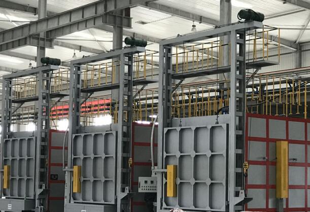
Gas Trolley Heat Treatment Furnace For Tungsten And Molybdenum Products
1. Equipment application: This series of gas trolley heat treatment furnaces are periodic operation furnaces, which are suitable for heat treatment of materials such as tungsten and molybdenum products and various chemical products.
2. Equipment composition: The gas trolley heat treatment furnace is mainly composed of steel furnace body, full fiber lining, furnace door, trolley, combustion system, air intake pipeline, smoke exhaust pipeline, sealing device and automatic control system.
3. Equipment features:
3.1. Furnace pressure control, smoke exhaust and waste heat recovery system:
3.1.1 Furnace pressure control system: Whether the pressure in the furnace is controlled or the quality of the control determines whether the temperature in the furnace is uniform and the thermal efficiency is high or low. The furnace pressure control system is composed of furnace pressure measuring device, pressure transmitter, control instrument and large diameter high temperature smoke valve. It can control and adjust the pressure in the furnace with the change of the heat supply, so that the furnace pressure is controlled at the best value, which not only ensures the full utilization of the hot air in the furnace, but also ensures that the cold air outside the furnace will not be sucked in large quantities, so as to save energy and uniformity. effect of furnace temperature. When the power is off, the smoke valve can be closed.
3.1.2. Smoke exhaust system: The heat treatment furnace of this trolley adopts the upper exhaust method to exhaust smoke. There is a smoke outlet on the rear wall of the furnace, and the main flue of the workshop is entered through a pipe.
3.1.3 Waste heat recovery system: There is an air heat exchanger (cylindrical metal radiant heat exchanger) at the rear of the flue gas outlet. Through the heat exchange between the flue gas and the air, part of the heat of the flue gas is recovered to increase the temperature of the combustion air. Combustion-supporting air temperature is controlled at 300℃, which can save energy by about 20%.
3.2. Control system part:
3.2.1 Main control functions:
In order to ensure the flexibility of the heating system and meet the different heating requirements of the workpiece. The combustion of the furnace adopts fully digital combustion technology – continuous control technology. Individual adjustment and control of each burner.
3.2.2 Furnace temperature control:
The primary signal collected by the thermocouple enters the recorder and the temperature control meter, the temperature control meter performs PID calculation, and the output signal of the intelligent meter controls the corresponding air solenoid butterfly valve, that is, the size of the burner in each area is controlled to realize the temperature control of each area;
●The gas flow is automatically proportionally adjusted through the air-fuel proportional valve, thereby ensuring a reasonable air-fuel ratio;
●Two K-type thermocouples are used for temperature control, one for each zone.
●Recording instrument records all control temperature signals.
3.2.3. Temperature before and after the heat exchanger:
●Use 2 K-type thermocouples to measure;
●The flue is over-temperature alarm, and the action of mixing cold air is implemented;
3.2.4 The temperature of the hot air main pipe:
●Use 1 K-type thermocouple to measure;
●Over temperature alarm; instrument display.
3.2.5 Natural gas mains pressure:
●The pressure detection of natural gas main pipe; instrument display.
3.2.6 Air Mains Pressure Control:
●In order to ensure better combustion stability, a pressure detection device is installed on the combustion air main pipe, and the fan is controlled by the frequency converter to ensure the stability of the wind pressure and the supply of air volume;
●Interlock alarm function of low air main pressure;
3.2.7 Furnace pressure control:
The furnace pressure is adjusted by means of the flue gate valve, and the furnace pressure is controlled at a slight negative pressure (0~-30Pa);
●Set differential pressure transmitter to detect;
●The furnace pressure high and low alarm;
3.2.8 Auxiliary equipment for combustion safety:
The gas main pipe is equipped with a quick shut-off valve, which forms an interlock with the set high and low pressure switches to ensure the safe combustion of the system.
3.2.9 Air-fuel ratio setting and adjustment:
Set the best air-fuel ratio, organize combustion reasonably, ensure uniform furnace temperature, control the air excess coefficient α value below 1.1, and the proportional valve has automatic control and manual adjustment functions.
3.2.10 Safety interlock control logic:
Because the fuel of this furnace is natural gas, the safety chain logic is more important, and the following items are mainly designed:
●Automatically cut off natural gas supply in case of power failure and major failure;
●Gas pressure control chain logic;
●Air manifold pressure control interlock logic.
4.Control system: composed of on-site acquisition facilities and intelligent instruments
4.1 Instrument:
●The furnace area instrument automation system, combustion control system and electrical automation control system are composed of on-site acquisition facilities and intelligent instruments. It mainly completes temperature, pressure, flow display, control, data communication, data acquisition, important logic control, etc., such as: cut-off, purge, ignition normal/fault, etc.
●In addition to the temperature signal entering the recorder, other temperature, pressure, and other special display instruments are also provided.
●The instrument cabinet is equipped with a flashing alarm.
4.2 Electrical control system:
Electrical control completes the control of combustion fan, trolley, furnace door, sealing, combustion system power distribution, instrument and electrical system power distribution and other parts. All are done in the control cabinet. The electrical control system includes electrical control and low-voltage power distribution within the furnace area. The furnace area is all powered by low voltage (380V/220VAC).
4.3 Scope of control:
Combustion fan control: use frequency conversion control
Trolley drive control: set the trolley limit switch, forward, backward, front in-position, rear in-position alarm and indication.
Furnace door lift control: adopt jog control, set furnace door limit switch, raise, lower, upper position, lower position alarm and indication.
The trolley, furnace door and sealing equipment are interlocked with each other.
Feeding: entering the trolley – lowering the furnace door – sealing
Discharge: open seal – lift furnace door – trolley
Purge program: After the fan is turned on, it will automatically enter the purge program. At this time, the control system does not allow ignition. After the purge is completed, the ignition conditions are met, ignition can be implemented, and the temperature control stage is entered.
4.4 Control function settings:
Individual control and interlock control of controllable equipment within the furnace zone;
Combustion system power distribution;
Instrumentation system power distribution;
The furnace door and the trolley are controlled by manual control and interlocking functions. The control box is placed in front of the control outdoor furnace to realize manual operation to control the lifting of the furnace door, the entry and exit of the trolley, and has a fault alarm function.
40Cr Steel Quenching And Tempering Treatment Process Nitriding Furnace Safety Operation Rules Effect 0f Annealing Temperature On Nanocrystalline Incoloy800
Contact us
Your email address will not be published. Required fields are marked *